8.1
Completion and mounting of the reflective cover
8.1.1
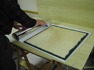
Apply reflecting foil to the reflective cover
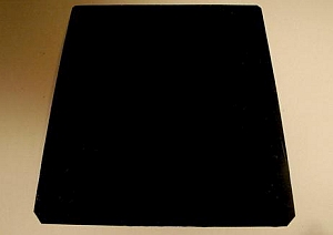
The reflective cover was already cut from 8 or 9 mm plywood and its upper side and edges have been painted (see appendix C). The inner side has been sanded and dusted.
The reflective side is covered with adhesive reflecting foil and gets trimmed afterwards.
Important: During the application, the temperature of the foil must be about the same as the room temperature.
| 1 |
0:00 |
Prepare the application of the foil |
| 2 |
0:48 |
Begin to separate the anti-adhesive paper from the foil |
| 3 |
1:16 |
Apply the foil to the plywood panel |
| 4 |
2:40 |
Remove dust grains from under the foil |
| 5 |
2:59 |
Complete applying the foil |
| 6 |
4:02 |
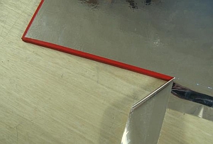
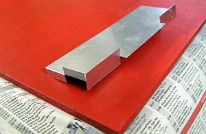
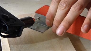
Trim the edges of the foil using cutting aid Jig 8.1. Hold the knife at a low angle |
|
 |
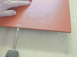
8.1.2
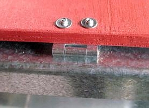
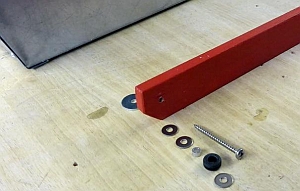
Reinforcing the reflective cover and drilling holes for screws
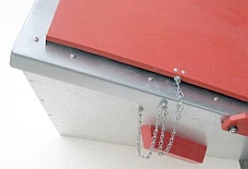
The reflective cover is reinforced by two rivets 20 cm from the back on both sides. This prevents the plywood from splitting when the screws are set from the side
- The left screw will hold the stop chain, which stops the cover from opening too wide
- The right screw holds the reflector support
|
 |
 |
|
| 1 |
0:00 |
Use hole gauge Jig 8.2 to mark the holes on one side of the cover |
| 2 |
0:24 |
... marking the holes on the other side
(The wood grain visible on the painted side should run parallel to the side edges.) |
| 3 |
0:38 |
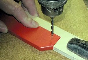
Drill 3.2 mm holes for the reinforcing rivets |
| 4 |
0:56 |
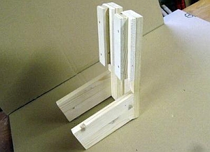
Put the reflective cover in an upright position, with the holding device Jig 8.4 and then set the reinforcing rivets No. 2 with washers No. 11 |
|
 |
8.1.3
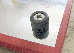
Screwing plastic rings to the reflective cover
To avoid damaging the reflective foil, attach one supporting ring Nr. 15 with a wood screw No. 6b to the underside of each front corner of the reflective lid
| 1 |
0:00 |
Remove positioning appliance Jig 8.6b from Jig 8.6a, Use it to mark the holes for the plastic rings. |
| 2 |
0:35 |
The screws are already set in the rings* |
| 3 |
0:37 |
If the screws turn out to be too long for the cover, place one or two washers underneath |
| 4 |
0:54 |
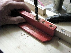
Just slightly pre-drill the 3.2 mm holes. Do not use the drill stop, as it would damage the foil |
| 5 |
1:03 |
Tighten the screws by hand. Beware of overwinding |
| |
|
* The placing of the screws into the plastic rings has not been filmed:
| Step 1: |
|
Drill a 2mm hole to a depth of 1cm into a random piece of hard wood |
| Step 2: |
|
Put the screw through the hole of the plastic ring |
| Step 3: |
|
With a hand screwdriver fasten the screw until the screw head is sunk about 2 mms |
| Step 4: |
|
Remove the screw with the ring. It can now be fastened to the reflective lid |
The pre-drilled hole can be used until it is worn out
|
|
 |
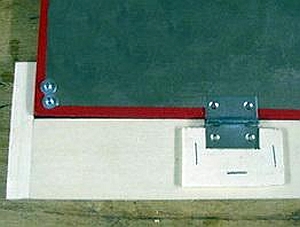
8.1.4
Riveting the hinges to the reflective cover
| 1 |
0:00 |
Set a support under the cover |
| 2 |
0:23 |
Drill one 3 mm hole for each hinge using gauge jig 8.3 |
| 3 |
0:48 |
Loosely fix each hinge with one rivet |
| 4 |
1:32 |
Align the hinges. Then drill the remaining holes and rivet |
|
 |
8.1.5
Mounting a stay to the reflective cover
| |
|
Drill a hole for the screw. Use screw No. 9 to fix distance sleeve No. 5 to the reflector cover |
|
 |
8.1.6
Riveting the hinges of the reflective cover to the glass frame
| 1 |
0:00 |
Use appliances jig 8.5 to position the cover. Then mark one hole for each hinge with a circle |
| 2 |
0:15 |
Punch the center of the circles |
| 3 |
0:18 |
Drill one 3.2 mm hole at the marked places at least 6 mm deep through both hinges. Then fix each hinge with one rivet No. 1 each |
| 4 |
0:27 |
Now drill the remaining holes and rivet |
|
 |
8.2
Mounting the supports
8.2.1
Drilling screw holes in both supports
In the glass frame support for the Ls and in the reflector supports for the Ls and Lw, the holes for the screws with which
they are fastened are still missing. In the reflector supports for the Ls and the Lw theholes are also missing, which receive the socket of the reflector cover.
| 1 |
0:00 |
Mark the screw hole on one of the supports 15 mm from both edges |
| 2 |
0:20 |
Align jig 8.6b (not Jig 9.2, as this No was changed) and fix it to the drilling table |
| 3 |
0:47 |
Drill the holes of both supports |
| 4 |
1:10 |
Attach jig 8.6a to the box column drill. The marked short strip corresponds to the thick part of the reflector support |
| 5 |
1:39 |
To drill the five holes, push the reflector support to the next mark |
| 5 |
2:05 |
Sand even the drilled strip with coarse sandpaper at low pressure |
|
 |
8.2.2
Mounting the folded angle plate to the support of the glass frame of the Ls
The angle plate was already cut, drilled and folded in Sect. 2.6.3 - 2.6.5. Now it is fixed to the support of the reflective cover.
| 1 |
0:00 |
Place the folded angle plate on the support and then bend the flange with force |
| 2 |
0:32 |
Drill 3.5 mm holes into the support through the pre-drilled holes in the angle plate |
| 3 |
1:08 |
Apply the rivets No. 2 from the side of the angle plate |
|
 |
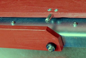
8.2.3
Screwing the reflector support to the glass frame
| 1 |
0:00 |
Drill a 2.5 mm hole approx. 25 mm deep through the hole on the right side of the metal frame into the wooden glass frame |
| 2 |
0:18 |
Put all parts on the screw exactly as shown:
No. 10 Woodscrew
No. 13 Washer
No. 15 Plastic ring
No. 4a Distance sleeve*
No. 13 Washer
No. 13 Washer
Plywood Support
No. 14 Washer
* The distance sleeve placed in the plastic ring prevents it from being compressed too much |
| 3 |
0:55 |
Screw on the support |
|
 |
8.2.4
Correcting a skew support
| 1 |
0:00 |
Perhaps occuring problem: the support stands of the Reflektor cover |
| 2 |
0:03 |
Take it off again |
| 3 |
0:06 |
Insert a washer No. 14 (or two) to adjust the support |
| 4 |
0:09 |
The appliance jig 8.7 keeps the washer in its position while the screw is being inserted |
| 5 |
0:12 |
Push the wascher behind the hole |
| 6 |
0:21 |
Fix the support again |
|
|
8.2.5
Mounting a support stop
To ensure that the reflector support does not happen to be placed backwards, a distance sleeve is placed behind the support as a stop
| |
- |
Drill a 3 mm hole approx. 2.5 mm deep and Set screw No. 7 to fix distance sleeve No. 4b |
|
|
8.2.6
Mounting the glass frame support for the Ls and support stops
| 1 |
0:00 |
Drill a hole through the already existing hole on the left side of the glass frame with a 2.5 mm drill |
| 2 |
0:06 |
Screw on the reflector support using all parts shown in Clip 8.8 in the right sequence |
| |
- |
Remove two screws on the upper left flap of the outer box. (No video clip) |
| 3 |
1:11 |
If the wooden frame turns out to be very hard, drill the two existing holes with 2.5 mm drill right through the glass frame |
| 4 |
1:28 |
Insert screws No. 7 with distance sleeves No. 4a |
|
|
8.3
Mounting the safety chains
8.3.1
Mounting the safety chains part 1
| 1 |
0:00 |
If needed, widen the chain links, so that screws or rivets fit |
| 2 |
0:20 |
Measure the length of the chain for the glass frame and transfer it to the wood strip jig 8.8 |
| 3 |
0:54 |
Loosely rivet the chain to the side of the box |
| 4 |
1:25 |
While fixing the rivet, pull the chain into the direction it will be pulled to later, when lifting the glass frame |
| 5 |
1:43 |
Drill a 2.5 mm hole 20 mm deep through the existing hole on the left side of the glass frame |
|
|
8.3.2
Mounting the safety chains part 2
| 1 |
0:00 |
Drill a 2,5 mm hole approx. 5 mm deep into the reflective cover |
| 2 |
0:17 |
Measure the length of the reflective cover chain, mark it on jig 8.7 and cut the chain to measurement |
| 3 |
0:43 |
and cut the chain to measurement Jig 8.8 |
| 4 |
1:03 |
Fasten the chain with woodscrew No. 8 and washer No. 12 to the reflective cover |
| 5 |
1:39 |
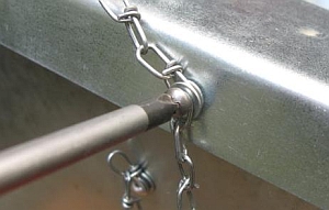
Fasten both free chain ends with wood screw Nr. 9 and three washers
No. 12. Attach the chains exactly as shown in the picture |
| 6 |
2:44 |
Check the chains: They must retain some clearance |
| 7 |
2:57 |
Both safety chains in function. |
|
 |
8.4
Cutting the hot plate from offset plate and painting it
The hot plates have the same shape as the bottom of the inner boxes, both for Ls and Lw. They are however 5 mm smaller in both directions
The width of the hot plate for the Lw exceeds the one for the Ls by 360 mm
| 1 |
0:00 |
To make a template for the hot plates of the Ls and the Lw, mark the sizes of the plates for the Ls and the Lw on an offset plate |
| 2 |
1:29 |
To make hot plates for the Ls, cut notches in the edges of the Lw template |
| 3 |
1:35 |
Label the templates as Ls T and Lw T for later serial production |
| 4 |
1:48 |
Use the templates to mark further hot plates. Cut the sheets to size |
| 5 |
3:16 |
Cover the hot plates with solar paint. When the paint has dried, turn them over to paint the other side |
| |
- |
Trim the corners of the hot plates. (no video clip) |
|
 |
8.5
Finishing touches
| 1 |
0:00 |
Tap sharp corners gently with a hammer to round them off |
| 2 |
0:19 |
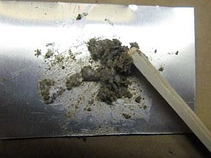
Make putty from fine sand and cold glue |
| |
- |
Use the putty to close possible gaps in the corners of the glass frame. Use a kitchen knife or a wooden stick to apply it. Remove excess putty with a dry rag and then clean with a wet rag. (no video clip) |
|
 |
| |
- |
Fasten the third hinge together with the other two hinges to the reflective cover. Use jig 8.3 (no Video Clip) |
| |
- |
Remove the central screw in the top flap of the back panel. The hole will be concealed by the hinge |
| 1 |
0:00 |
When fastening the hinges to the glass frame, first tighten the two outer hinges. Align the middle hinge with a long pressure plate to the lateral hinges |
| 2 |
0:11 |
Mark holes, drill and place rivets as established |
|
|
| 1 |
0:00 |
Fasten the spacer sleeve to the support rest: Prick screw hole as shown in the video and drill a 3.5 mm hole. Fix the distance sleeve No. 5 with woodscrew No. 9 |
| 2 |
0:24 |
Drill a 3.5 mm hole into the glass frame support as shown in the video clip |
| 3 |
0:32 |
Fasten the support with all parts in the order shown (see Clip 8.8)
No. 10 No. 13 No. 5 No. 14 support No. 14 |
|
 |
Congratulations!
Having arrived here means: You have done it! The path will at times have been troublesome und tedious. You will hardly recall all the many difficulties and tricky places you had to master, so this printed manual is there for you to look them up and make repetition easier.
We feel certain, that you will soon have memorized the sections of the building process. In case you should have forgotten something, the extensive video will help you. With only one click, every single step of the process is at your command.
As soon as you will begin with the serial
production, you will come to value the various jigs. They facilitate the entire work process and ensure precise results, more so than you can fathom at first.
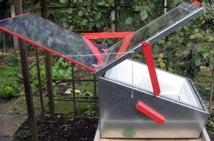
This manual enables you to build without much technical expense powerful, easy to operate and appealing solar cookers that compare favorably with industrially manufactured cookers.
Should you intend to reproduce the LAZOLA cooker without following our suggestions in detail, we do not mind at all. In this case however, you should watch the short conclusion in chapter 10 of the information regarding the construction manual:
This will save you needless disappointments.
Should further questions or lacks of clarity arise, do not hesitate to request our counsel.
Yours, the LAZOLA Initiative, Paderborn